
MELAN MEASUREMENT & CONTROL INSTRUMENTS (SHANGHAI) CO., LTD.
|
| Place of Origin: | China |
| Model Number: | MLF |
| Minimum Order Quantity: | 1pc |
|---|---|
| Price: | Negotiation |
| Packaging Details: | In Carton or Wooden Box |
| Delivery Time: | 7-10 working days |
| Payment Terms: | T/T |
| Supply Ability: | 500pcs per month |
| Product Name: | Electro Magnetic Flow Meter | Pipeline Diameter: | DN15-DN2000 |
|---|---|---|---|
| Accuracy: | 0.5% Or 0.2% | Flange: | GB/ANSI/JIS/BS/Others |
| Velocity Range: | 0.3~10m/s | IP Class: | IP65/IP67/IP68 |
| Highlight: | Electromagnetic Seawater Flow Meter,10m/S Seawater Flow Meter,IP65 Seawater Flow Meter |
||
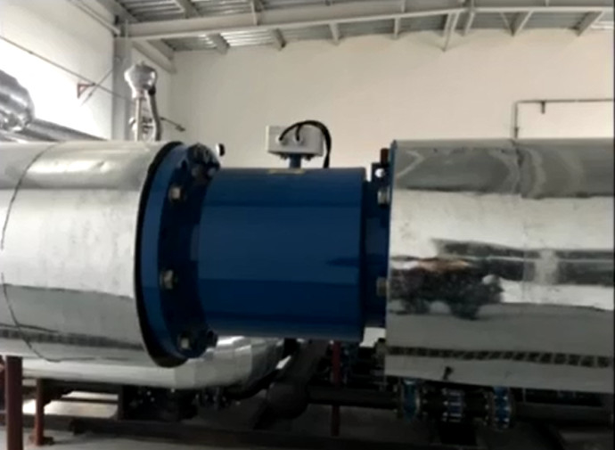
Electromagnetic Flow Meter Manufacturer / Seawater Flow Meter
1. Introduction
MLF electromagnetic flowmeter works according to Faraday's law of electromagnetic induction, and is composed of sensors and converters. Used to measure the conductivity of liquid or solid. In general, its conductivity should be greater than 5μs/cm (tap water and raw water conductivity is about 100 ~ 500μs/cm), and it can also be used to measure acid, alkali, brine, pulp or pulp and other media. However, these media cannot contain a large amount of magnetic substances and bubbles.
MLF electromagnetic flowmeter is an instrument for measuring liquid fluidity. Widely used in metallurgy, chemical industry, paper making, environmental protection, petroleum, textile, food, urban management, water plant and other industries.
2.Working Principle
The principle of the sensor is based on Faraday’s law of electromagnetic induction.
It is installed a pair of detection electrodes on the pipe wall,where the measurement pipe axis and magnetic field lines are vertical. When the conductive liquid cuts magnetic field lines and produces induced electromagnetic force.Which can be measured by the two electrodes on the
meter pipe.The result can be calculated by formula: Induced electromotive force,(flow signal) E=KBDV
E——Induced electromotive force,V;
K——meter constant;
B——Magnetic flux density,T;
D——Internal diameter of measuring pipe,m;
V——Average velocity of pipe section,m/s.
MLF Series Electromagnetic Flow Meter
Assume the volume of liquid as qv(m3/s),qv=πD2V/4),so in the formula E=(4kB/πD)qv=kqv,
K is meter constant,K=4kB/πD.
Actually, the electromagnetic flow meter consists of two parts, transmitter and sensor, the measuring electrodes inspect the electromotive force, and transmit to the converter, the converter provides excitation current.
E is usually called a flow signal, after processing the flow signal by converter, output 4~20 mA/pulse(or frequency) signal which is proportional to the flow rate, then the flow rate recording,adjusting can be achieved.
3. Specification
| MLF Type | Divided Type | Integrated Type | Explosive Proof Integrated Type | Battery Powered Type | Heat Energy Type |
| Accuracy | ±0.2% or ±0.5% | ||||
| Pipeline Diameter | DN10-DN2000 | DN10-DN600 | DN25-DN2000 | ||
| Flange | GB, ANSI, JIS, BS, Others | ||||
| Pressure | DN10-DN600 1.0 1.6 2.5 4.0MPa | ||||
| DN700-DN2000 0.6 1.0 1.6MPa | |||||
| Liner Material | CR, PTFE, PU, Hard Rubber, PFA, FEP(F46) | ||||
| Conductivity | ≥5µs/cm(Please contact us if it is less than 5µs/cm) | ||||
| Electrode | 316L SS, Hb, Ta, Ti, Hc, Tungsten Carbide, Others | ||||
| Protection Class | IP65, IP66, IP67, IP68 | ||||
| Medium Temperature | -25~180℃ (Please refer to liner material) |
-25~80℃(Please refer to liner material) | -25~180℃ (Please refer to liner material) |
||
| Ambient Temperature for Accuracy Influence | <±0.1%/10℃ or <±0.25%/10℃ at the ambient temperature of -25~60℃ | ||||
| Repetability | ≤±0.1% or ±0.25% | ||||
| Analog Output Error | ≤±0.02mA | ||||
| Velocity | 0.3~10m/s | ||||
| Electrical connection | M20x1.5 Seal Cartridge, GB1/2, NPT1/2 | ||||
| Output | 4-20mA, Pulse, RS485, Hart, Profibus | ||||
4. Configuration
| MLF Series Electromagnetic Flow Meter Configuration | |||||||||||||||||||||||
| Model | MLF | ||||||||||||||||||||||
| Sensor Installation | S | Flange Type Sensor | |||||||||||||||||||||
| C | Insertion Type Sensor | ||||||||||||||||||||||
| O | Others | ||||||||||||||||||||||
| Pipeline Diameter | 10 | 10mm | |||||||||||||||||||||
| 15 | 15mm | ||||||||||||||||||||||
| 20 | 20mm | ||||||||||||||||||||||
| ...... | |||||||||||||||||||||||
| 2000 | 2000mm | ||||||||||||||||||||||
| Electrode Installation | F | Standard Fixed Type | |||||||||||||||||||||
| Electrode Material | A | 316L SS | |||||||||||||||||||||
| B | Hb | ||||||||||||||||||||||
| C | Ta | ||||||||||||||||||||||
| D | Ti | ||||||||||||||||||||||
| E | Hc | ||||||||||||||||||||||
| F | Tungsten Carbide | ||||||||||||||||||||||
| G | Others | ||||||||||||||||||||||
| Liner Material | R | Rubber | |||||||||||||||||||||
| P | PTFE | ||||||||||||||||||||||
| O | Others | ||||||||||||||||||||||
| Pipe Material | B | 304 SS (Standard) | |||||||||||||||||||||
| C | 316 SS | ||||||||||||||||||||||
| Flange Type | G | GB (Standard) | |||||||||||||||||||||
| A | ANSI | ||||||||||||||||||||||
| J | JIS | ||||||||||||||||||||||
| B | BS | ||||||||||||||||||||||
| O | Others | ||||||||||||||||||||||
| Flange Material | A | 304 SS | |||||||||||||||||||||
| B | 316 SS | ||||||||||||||||||||||
| C | #20 Carbon Steel (Standard) | ||||||||||||||||||||||
| Cover Material | D | 304 SS | |||||||||||||||||||||
| E | 316 SS | ||||||||||||||||||||||
| F | Carbon Steel+ Epoxy Metallic Paint (Standard) | ||||||||||||||||||||||
| Matching Flange | 0 | Without Matching Flange (Standard) | |||||||||||||||||||||
| 1 | With Matching Flange | ||||||||||||||||||||||
| Ground Ring | 0 | Without Ground Ring (Standard) | |||||||||||||||||||||
| 1 | With Ground Ring | ||||||||||||||||||||||
| Rated Pressure | 10 | 1.0MPa | |||||||||||||||||||||
| 16 | 1.6MPa | ||||||||||||||||||||||
| 25 | 2.5MPa | ||||||||||||||||||||||
| 40 | 4.0MPa | ||||||||||||||||||||||
| Working Temperature | E | ≤60℃ | |||||||||||||||||||||
| H | ≤180℃(Divided Type) | ||||||||||||||||||||||
| Type | I | Integrated Type | |||||||||||||||||||||
| D | Divided Type | ||||||||||||||||||||||
| Output | P | Pulse | |||||||||||||||||||||
| A | 4-20mA | ||||||||||||||||||||||
| G | RS485 | ||||||||||||||||||||||
| H | Hart | ||||||||||||||||||||||
| Q | Others | ||||||||||||||||||||||
| Power Supply | 0 | 220VAC | |||||||||||||||||||||
| 1 | 24VDC | ||||||||||||||||||||||
| 2 | Battery-powered | ||||||||||||||||||||||
| Protection Class | 0 | IP65 (Integrated/Divided Type) | |||||||||||||||||||||
| 1 | IP67 (Divided Type) | ||||||||||||||||||||||
| 2 | IP68 (Divided Type) | ||||||||||||||||||||||
| Other Features | R | Heat Energy Function | |||||||||||||||||||||
| P | With PT1000 | ||||||||||||||||||||||
| B | Without PT1000 | ||||||||||||||||||||||
| Explosion Proof | 0 | None | |||||||||||||||||||||
| EX | Explosive Proof | ||||||||||||||||||||||
5.Instrument Inspection and Maintenance
Electromagnetic flow meters have a self-diagnosis function. In addition to power and hardware circuit failures, the system also alerts to other faults in general use. This information is prompted in the lower right corner of the screen.
1 Maintenance and repair
a) The sensor installation site should comply with section IV requirements, please keep the housing clean;
b) The transmitter should be placed in a clean, ventilated and dry place;
c) The instrument needs to be checked every two years and for high-precision users, the instrument needs to be submitted for review.
2 Transport and storage
a) The instrument must be packed before transport and handled with care.
b) Storage sites must be dry and ventilated to avoid the erosion of corrosive gases, and the ambient temperature should not be too low or too high;
c) Storage time should preferably not exceed three years.
3 out-of-the-box inspection
a) The package cannot be opened with a heavy hammer and care should be taken not to damage the instrument
b) Check the contents carefully according to the packing slip.
6. Packing
![]()
Contact Person: Ms. Nancy Zhao
Tel: 0086-21-57652429
Fax: 0086-21-57652430
Stable Performance Vortex Flow Transmitter DN100 RS485 Output ±1.0% Accuracy
6 Inch Vortex Flow Meter Vortex Flow Measurement For Gas Steam Water
Convenient Vortex Steam Flow Meter / High Stability Vortex Air Flow Meter
Thread Type Vortex Flow Meter with Temperature Pressure Compensation
Low Flow Electromagnetic Flow Meter Divided Type Ex-Proof JIS 10K Flange
High Performance Divided Insertion Type Magnetic Flow Meter For Big Size Diameter
4 Inch Compact Electronic Magnetic Flow Meter With Modbus RS485 Output
Multi - Language Electronic Magnetic Flow Meter Low Conductivity Measurement
Self - Diagnosis Intelligent Pressure Gauge And Pressure Transmitter
Industrial Gauge Pressure Transmitter Explosion Proof Pressure Transmitter
LED Display Industrial Pressure Transmitter 12VDC - 36VDC Power Supply
Stable Diffusion Silicon Gauge Pressure Transmitter 4 - 20mA Hit - Resistant Capacitance


